Athletic Trainer Pads
Introduction
Our proposed athletic trainer pads allow users to improve upon their speed, accuracy, and agility in a very simple drill. We use four identical looking pads that flash LED lights and respond to touch. The purpose is to determine the reflexes of the user based on how much time passes from the pad’s LED being lit to the user hitting the pad. There is an app interface that wirelessly takes in this data, stores it, determines trends over time, and alters the drill based on user performance.
Problem Statement
Various fields of human physical activity (Sports, physical therapy, military, and school testing) use agility drills to test the subject’s speed, endurance, and reaction time. Despite the large emphasis of these drills in the world of physical health, there is no standard for how to collect and analyze that data through certain movements. Furthermore, these drills depend on human direction and timing, which inherently leads to error. The lack of standardization in tracking results and the inevitable error present creates difficulties in seeing progression over time.
Project Overview
We created Athletic Trainer Pads that serve as a standard to test speed and reflex. The pads themself direct a speed-based agility drill that connects to a website interface that analyzes and stores the user’s data metrics over time. This allows us to move beyond traditional methods of measuring speed and improving agility. The goal is to improve the quality of standard agility drills for users while increasing the efficiency of analysis for testers.
System Requirements
1. Button systems should provide visual cues to indicate when and where to strike
2. Button systems should detect and withstand a force applied
3. Device should be wireless and rechargeable
4. Button systems should communicate with one another via ESP-NOW
5. System should be capable of interfacing with a website via Wi-Fi
6. Accurate real-time data collection of reaction time
7. Website capable of time data storage with analysis of trends over time
Overall System Diagram
.jpg)
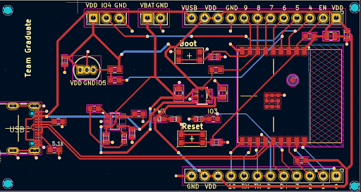
Hardware Overview
The overall hardware system of our proposed solution consists of five total button systems. One of the five button systems is established as the master system and the other four as the slave systems. Each button system has a protective mechanical casing providing a user-friendly striking surface and protecting the components from damage. This mechanical casing was designed using the CAD software SolidWorks and then produced using 3D printing. Materials utilized included clear resin for the dome casing and ABS-M30, a production-grade thermoplastic material, both of which offer high impact durability and water-resistance. The outer mechanical structure consists of three separate pieces: a base component, a clear dome casing that enables the user to visualize the lighting of the LED, and an outer casing that allows for the fastening of the three pieces together. The three pieces are held together via poles and screws that connect through them.
The base piece houses the ESP32-C3 board, Lithium-ion battery, addressable LED, and analog Hall Effect sensor which is mounted atop of the ESP32-C3. The only difference in hardware between the master button system and the slave button systems is its lack of an addressable LED and Hall Effect sensor. Each button system is wireless. Pre-programmed and battery powered, the buttons can all run the drill without any external connection.
The 3.7V Lithium-ion battery is responsible for powering the ESP32-C3 board, clock, the LED, and Hall Effect sensor mounted on the ESP32-C3 board. It is rechargeable via a USB-c port accessible through an opening in the outer casing. The addressable LED enables each slave button system to light up and indicate to the user when and where to push as the workout progresses. The push mechanism is enabled through the use of springs and a magnet attached to a protrusion incorporated in the design of the dome casing. As the user pushes down on the dome casing, the distance between the magnet and Hall Effect sensor decreases; when that change is detected, the sensor recognizes the touch and communicates it to the ESP32-C3 board. The springs will cause the dome casing and its associated magnet apparatus to return to its original position so that no further touch is detected after the initial push.
Software Overview
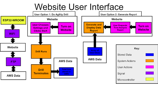
The overall software system of our proposed solution consists of communication between the boards via ESP-NOW, a website that the master board connects to via WiFi to, and an AWS bucket to store time data. ESP-Now operates within the 2.4 GHz band from the built in antennas on ESP32. The button systems will be separated by two meters, and ESP-Now supports this distance for communication between the boards. Throughout the drill, after the user hits the lit up touch pad, the button system will use ESP-NOW to communicate to the next button system to light up.
The drill is started and terminated in a master board that is not utilized as a button system. The master board uses its mac address to create a web server. From there, the user can either initiate a drill or do data analysis. If the user chooses to initiate a drill, a random order of 10 buttons will be sent to the master board. The master board will utilize this to determine the order of buttons to light up. If the user chooses to do data analysis, time data will be put into a bar graph. Individual bars will represent outcomes of each time the drill is run.
The time data for each time the drill had been completed is stored in an AWS bucket. Buckets are AWS cloud based storage that can be accessed via WiFi. Each time the drill is run, after the 10 lit up touch pads have been hit, the drill will terminate. The total amount of time the drill takes to complete will be from the time the first touch pad lights up until when the last one is striked. The master board will then use WiFi to communicate with the AWS bucket and put the total amount of time the user took into the bucket along with previous times.
Setup and Integration
The buttons are assembled by connecting the three separate pieces: the clear dome piece, the outer casing, and the base component. A compartment is located in the bottom of the base piece for placement of the circuit board with an additional compartment in the side of this piece to hold the battery with wires connecting it to the ESP32-C3 board. Finally, after being wired to the board, the led can be attached to the shelf found in the center of the base piece. The three pieces fit together via poles constructed in the design of the outer casing. These poles travel through holes found in the clear dome and base pieces to hold all three pieces together. Holes are, also, found in the base piece for placement of the springs with the top of the springs resting in holders in the clear dome piece. This connection is reinforced via the use of screws that screw in through holes in the base piece and through the length of the poles.
The buttons will be placed on the ground in a square, each button being two meters away from the two adjacent ones. The user will stand in the center of the four buttons and will touch whichever button lights up.
The user will start the drill by clicking the “Start” button on the website. After a 2 second delay, this will initiate the first button system to light up. The user will tap this pad, pushing on the clear part so that the pad detects a hit. The Button system will light off and another Button system will light up. The user will continue to touch the Button systems as they light up and the sequence of Button systems lighting up is in a random order each drill. Once the user has touched the lit up Button systems 10 times, the drill will end. All button systems will turn off and the total time the user took to complete the drill will automatically be stored online.
The user can additionally check their performance as they do multiple iterations by clicking the “Progress” button on the website. When this is done, a bar graph will be displayed showing the time the user took each time they participated in the drill. The user should be able to use these results to determine a general progress trend.
Future Directions / Enhancements
If given additional time, there are several enhancements we would aim to incorporate in future designs. Firstly, we would incorporate a means to mount the button systems on a surface to allow for the user to perform floor- or wall-mounted drills. This would enable more flexibility and diverse options in terms of user training.
To allow for further flexibility in terms of user training, we would develop and adopt several ways for the user to tailor their workouts to their preferences. This would include the possibility of users deciding their difficulty level, if they want to focus on a particular element of their training (such as a specific side, specific pattern of touches or movements, etc.), or if they want to implement an adaptive mode. The option of an adaptive mode would incorporate machine learning and allow for the user to improve on weak areas that the system identifies. In the adaptive mode, new workouts will be created based on data collected in the previous workout(s).
Furthermore, additional measures would be taken to expand upon data collection and analysis. Software would be developed to collect data regarding button position, time from one button press to the next, and an option for users to input physical characteristics such as age, weight, height, etc. This would enable more specific and personalized analysis reports for the user and machine learning could, again, be implemented to adapt workouts to this additional data. Another future enhancement we would seek to implement is the ability for the workout software to distinguish between multiple users. This improvement would allow for users to input their name at the start of the drill and the software will store the data as well as generate reports and workouts based solely upon the individual user. Finally, another significant development we would incorporate in future designs is a power saver mode that automatically turns on in between workout repetitions to reduce the load off of the battery and foster greater battery life.