NASA Requirements

The following requirements for the rover were set in the 2018 NASA Student Launch Handbook

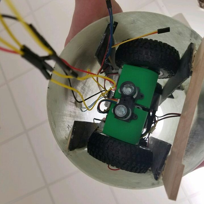
  1. Teams will design a custom rover that will deploy from the internal structure of the launch vehicle.
  2. At landing, the team will remotely activate a trigger to deploy the rover from the rocket.
  3. After deployment, the rover will autonomously move at least 5 ft. (in any direction) from the launch vehicle.
  4. Once the rover has reached its final destination, it will deploy a set of foldable solar cell panels.

System Block Diagram

System Block Diagram

The electrical control system consists of a PIC32MX395 microcontroller which talks to a LoRa module to receive commands and transmit the current system information such as altitude, orientation, and GPS coordinates of the rover. The Electronic Control System is comprised of 4 subsystems, a microcontroller, and a base station.


Subsystem Level

A closer look at individual subsystems

The Power Supply Subsystem uses two IMREN 18650 3.7V 3000mAh lithium manganese oxide batteries. A 3D printed housing provides short circuit protection. Built in circuitry in the motor drivers and linear regulators provides over current protection.

The Sensor Subsystem determines the rover's location, orientation, and velocity, relative to the Earth, the rocket, and objects in front of it. A LiDAR sensor is used for object avoidance. An accelerometer is used for orientation. A GPS sensor is used for location.

The Base Station consists of a laptop connected to a LORA module. The serial monitor on the laptop displays received data. The board has buttons that are used to send commands such as detonate and deploy.

The Remote Activation Subsystem is used to receive commands from the base station, transmit data to the base station, and to detonate the black powder charges. Electric matches are used as detonators for setting off the black powder charges that blow the nose cone off the rocket and allow the rover to exit the rocket tube.

The Motor Subsystem uses a single LEGO XL motor for each wheel for a total of four XL motors. The LEGO Power Functions XL motor is a brushed DC motor with an internal two-stage planetary gearbox. Two DRV8835 chips are used to control the speed and direction of each LEGO XL motor. The TI DRV8835 is a Dual Low-Voltage H-Bridge.

The Control Center for all the various rover subsystems is a PIC32MX795 microcontroller. This particular microcontroller was chosen for its ability to work with 8 byte data streams, which is required by some of the sensors, and the large number of remappable pins that are available for controlling various inputs and outputs.