The final, integrated system had the task of harnessing RF and traditional circuitry alongside software solutions to receive, beamstear, amplify, and process signals using Dr. Chisum’s PAFL antenna array. It would also implement multiple auxiliary components to assist with operation, such as power usage monitoring and motor deployment. The system begins with the motor control, which would deploy the lens to its proper location from the antenna array. Feedback on this distance would then be sent to the ESP32 so the proper weights for the beamformer could be set. Next, the testing apparatus, which consists of a signal generator connecting to a horn antenna to transmit a 23.8 GHz signal. This signal would then be received by the array of eight patch antennas, passed through a bandpass filter, and amplified using an LNA. The high frequency signal was then sent to the beamformer, where the proper weights were given to each individual signal and combined into one to be passed onto the power detector, where it was then translated to a DC value. The LNAs and beamformer were to be powered by the 4V and 2.4V regulators from the power system respectively. A 3.3V regulator, also from the power system, powered the rest of the components. The DC value would then be passed to the ESP32, where it was logged and processed. Lastly, two power monitoring circuits, one connected to the 3.3V circuit and one to the 4V circuit, would track the overall power usage of the system, reporting back to the ESP32.
The power subsystem exists to provide the proper power output to the rest of the system. There are two available power inputs for the board, the USB-C connector and a power line input provided from the greater CubeSat. This power line has a 5V/2A minimum expected in the final design. The power subsystem is able to switch between these two sources, with the USB-C being favored if both are plugged in. This is controlled by the switching transistor. The 5V is then stepped down to both 3.3V and 4V by two different voltage regulators. These three voltages are all that is necessary for the full project’s operation. Lastly a schottky diode is included to ensure the power path proceeds into the circuit and nothing is returned back to the power inputs.
The antenna control system exists to implement the particle swarm optimization algorithm by applying the beamforming coefficients determined by the PSO algorithm to our array of antennas in order to find the maximum gain solution. This will be accomplished by employing a lookup table on our MCU that has been created by running the PSO algorithm on an external laptop and sending the information to the MCU via SPI communication protocols.The MCU will in turn process and send relevant data collected from the antenna array back to the laptop in order to determine the direction of transmission from our test rig signal generators.
This system exists to capture transmission signals with our antenna array and then process the incoming data by filtering, beamforming, and applying gain so that the RF power can be detected via an RMS power detector. The output voltage proportional to the RF power will then be sent to the antenna control subsystem for further processing. Our system will operate at 22GHz so the corresponding passband of our filter will be approximately centered on that frequency. Additionally, we will apply a gain cascade via an LNA per patch antenna with an additional LNA after beamforming so that we achieve -20db allowing our power detector to work within its typical range.
The motor control and deployment subsystem exists to ensure proper positioning of the antenna and lens array once the satellite has reached orbit. The antenna array is calibrated to start at a 0.2 lambda distance in its undeployed state. At full deployment it will reach a 0.4 lambda spacing, the optimal place for the antennas. This is achieved through a stepper motor, driven by a controller. The motor will connect to the deployment mechanism through a gear assembly created by the IrishSAT team. An internal encoder will allow us to be certain of the exact deployment distance of the antennas and adjust the weights for processing the signal accordingly. The encoder signal is fed to the controller to guarantee the 0.4 lambda distance is met.
The testing apparatus includes the laptop and visualization screen for viewing our collected data. This subsystem also includes the horizontal path along which our source travels and is detected by our antenna array.
The board was designed to fit all components and routing in a 90mm x 75mm space. Due to a desired spacing of two wavelengths (at 23.8 GHz this corresponds to 25mm) between RF and DC components as well as the need for a continuous ground plane below RF elements this board was originally designed to have 4 layers with the top right corner being designated for RF. However, because of the cost and time required to produce an RF board the team decided to produce a simpler 2 layer board with only the DC compenents and move the RF components to a separate antenna board that was milled at Notre Dame in Dr. Chisum's lab.
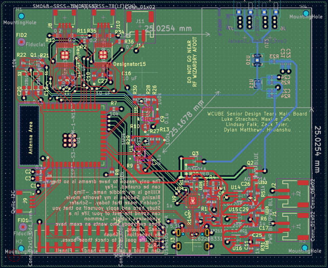
WCUBE Main Board
Software was written as a state machine which transitions through all the necessary procedures of our project. This begins with deployement of a lens using 2 stepper motors to a designated height upon the cubesat reaching orbit. Following lens deployment SPI communication is used to intitialize a Beam Forming Integrated Chircuit chip (BFIC) which provides our antenna array with the proper weighting. After initial setup our software routinely take measurements of our systems power consumption, and antenna out put power and send the data to the IrishSat Main flight computer via I2C communication. Additionally, for the demonstrative purposes of this porject our antenna power output data is also send to a laptop where a Matlab script is used to visualize the data.
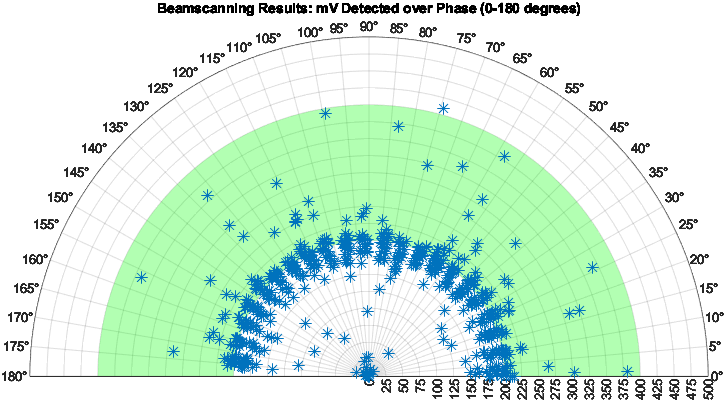
Matlab Visualization of Antenna Power Output