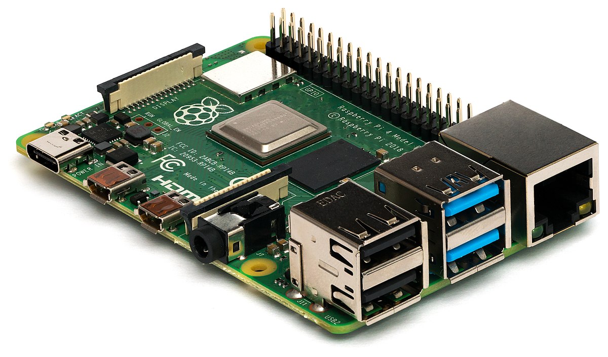
Raspberry Pi

Raspberry Pi
The Raspberry Pi will be reading and interpreting the data from the IMU, Decawave and Camera subsystems. The Pi will communicate via UART with our custom PCB. The PCB will rely the range finder information, information from the servo motors and communication from the zigbee module. The Pi will communicate with the IMU through I2C and the Decawave module through SPI. The camera will communicate by CSI. The camera module we are using comes with the Pi and it works natively with the Pi. The Pi is also in charge of doing the math for finding the location of the rovers. The Pi will receive information from the Decawave and calculate the location of the rovers based on this information. The Raspberry Pi will receive power from the PIC32 Custom Board. The on board voltage converter will step down our input voltage from 5V to 3.3V for the logic. The Raspberry Pi has an on-board clock which will be used to control the Decawave and IMU.


