Home
Project Overview
A bottom / top CAD image of the glider.
This year’s AIAA Design Build Fly (DBF) Competition challenges teams to design an autonomous glider that separates from a main aircraft mid-flight and lands as close as possible to a designated landing zone. Teams are scored based on the number of laps completed by the main aircraft, the glider’s weight, and its landing accuracy.
Partnering with the DBF Club at the University of Notre Dame, our Senior Design team was focused on developing the electronics system for the glider. While the DBF Club leads other aspects of the project, our group is responsible for integrating the embedded hardware and control systems to create a functional glider.
Our solution centers around a custom-designed printed circuit board featuring an ESP32 microcontroller, which interfaces with multiple onboard sensors and controls the aircraft’s servo motors. This system enables autonomous flight adjustments during descent. This project overview outlines the competition requirements, our high-level design approach, progress to date, anticipated challenges, and a preliminary cost summary.
Problem Statement
The AIAA Design Build Fly Competition has a list of requirements and constraints on the glider aircraft that must be met in order to be eligible for the competition.
To begin, the glider can have a maximum weight of 0.55 pounds (250 grams). Teams are allowed to determine means of flight control and navigation. However, no radio controlled receivers are allowed to be integrated onto the glider. The glider must fit between the two external fuel tanks on the airplane and be secured to the airplane for all stages of flight, except for the mission during which it is launched. There is a minimum gap of 0.25 inches between any part of the airplane fuselage and the wings of the glider. The glider must have strobe lights that turn on after it is released from the airplane. No points will be received if the lights turn on before launch, or fail to turn on after launch.
The glider must be launched from the airplane at an altitude of 200–400 feet above the ground. To achieve bonus points, the glider must release itself from the airplane and execute a 180-degree turn. Then, using a descending or gliding pattern of choice, the glider will land on the ground. If the glider comes to rest within one of the landing zones as shown in Figure 1, bonus points will be awarded. The scoring calculation is shown below in Equation 1.
Equation 1.
Figure 1.
Final Board Design
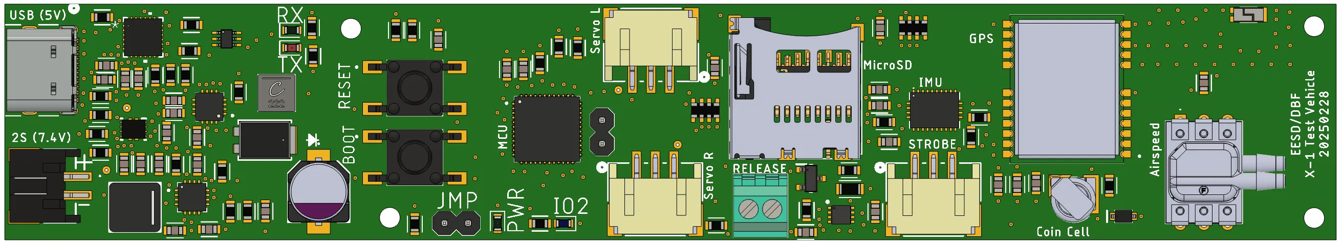
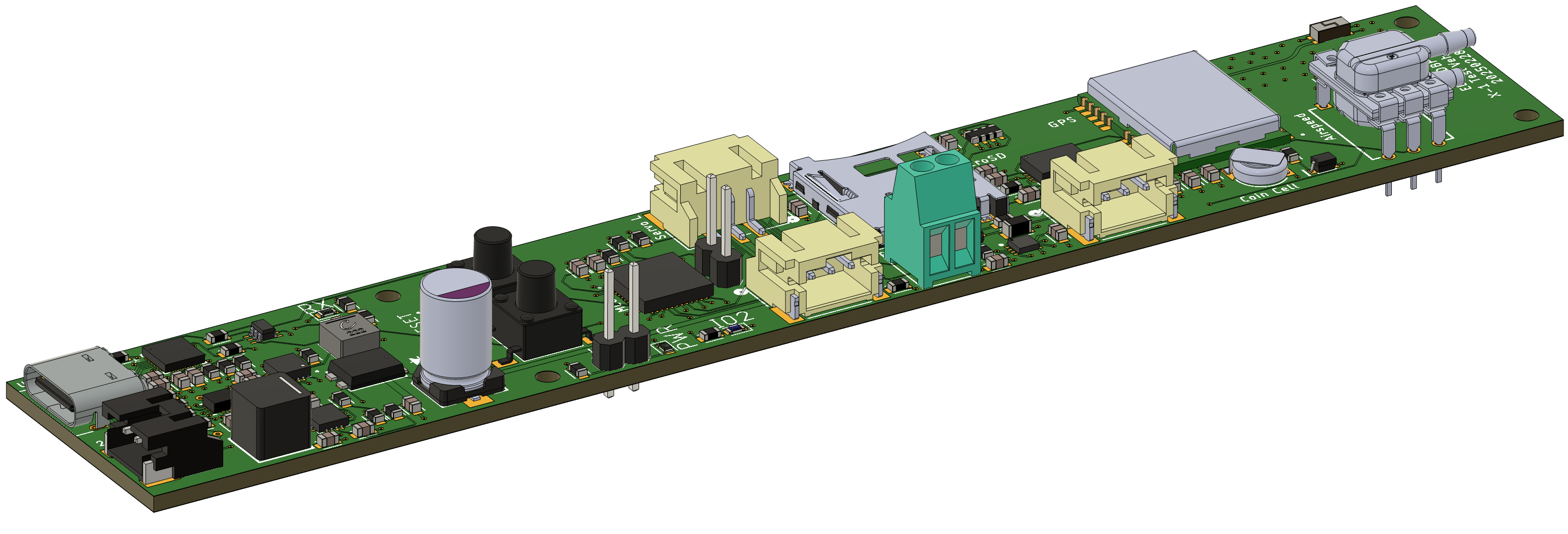
The PCB shown above was designed to meet the glider's size and weight constraints. It is built around an ESP32-PICO-V3 microcontroller and interfaces with onboard sensors via I2C and SPI. It also supports PWM control for servos. The layout includes impedance-matched RF routing for the GPS antenna, 4 layers for adequate power distribution, and small component footprints to reduce weight.
High Level Block Diagram
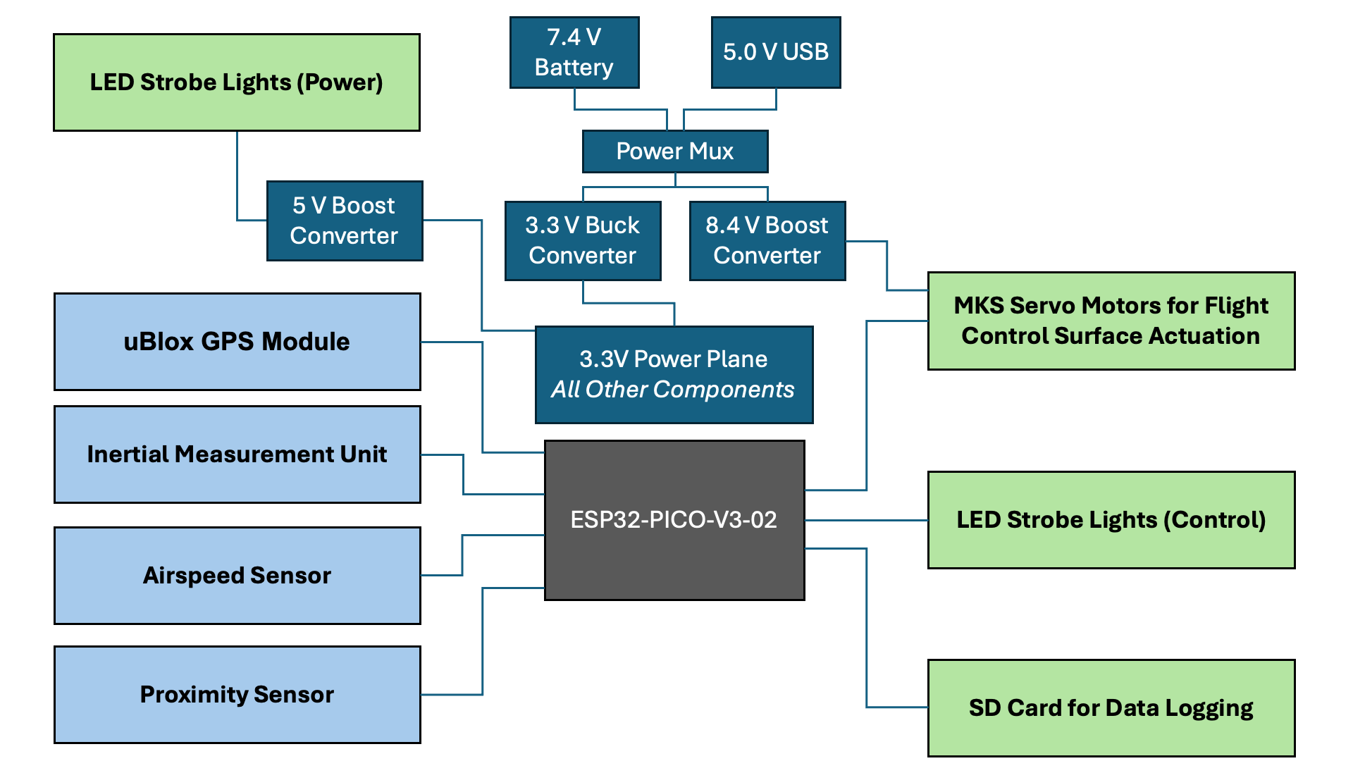
The block diagram above displays a high-level visual of the connections between the ESP32 microcontroller and its subsystems. These subsystems include voltage converters for power regulation, the inputs from the sensors to the ESP32, and the outputs from the ESP32 to the other peripherals.
Power Path Flow Chart
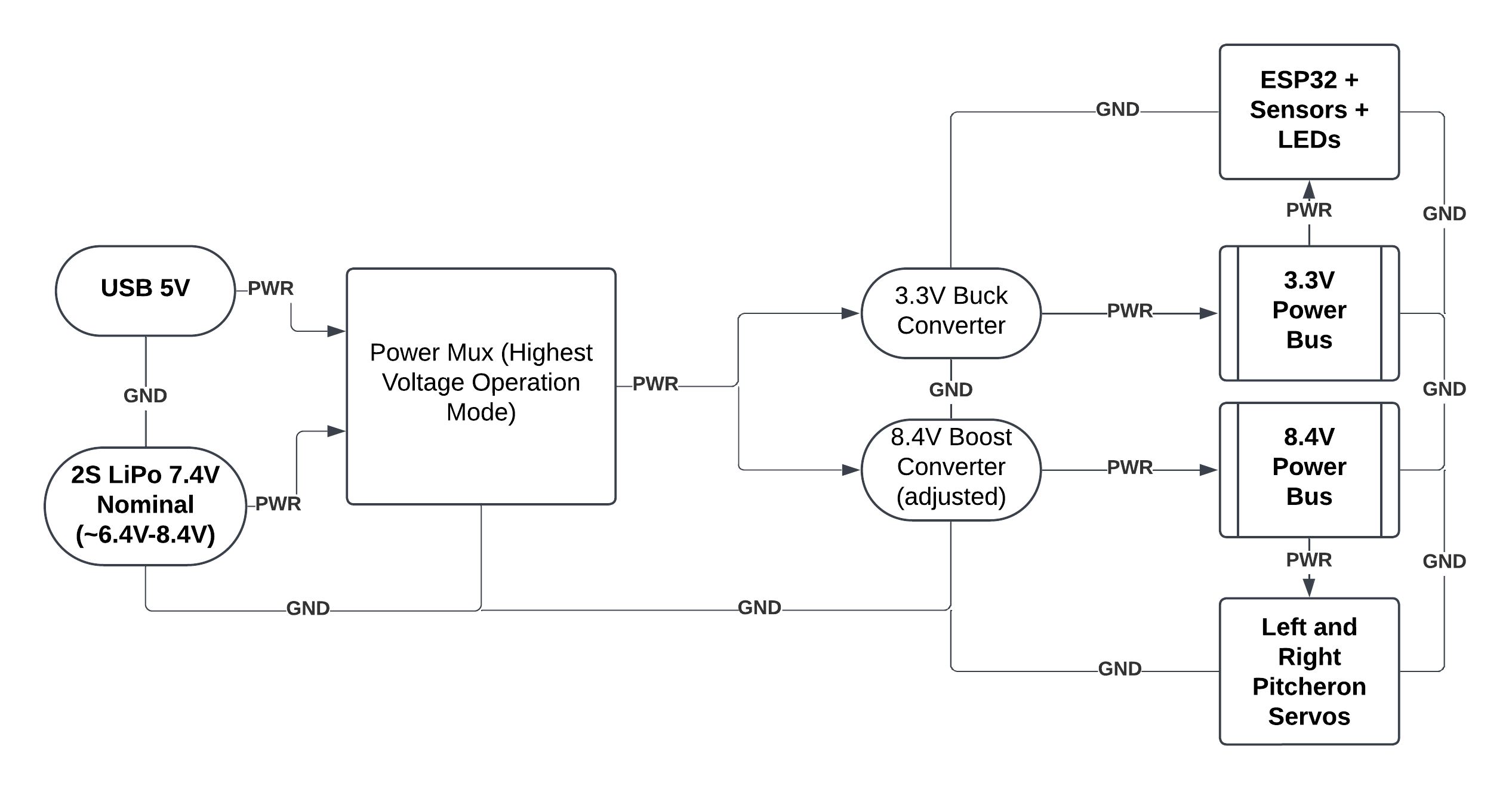
This flow chart shows the glider's power system. The board supports 2 inputs, USB and LiPo battery, and automatically selects the higher-voltage connection using a power multiplexer. Voltage regulators then convert this to required levels for the different subsystems: 3.3V for the ESP32 and sensors, 5V for LEDs, and 8.4V for servo motors.
Full Code Flow Chart
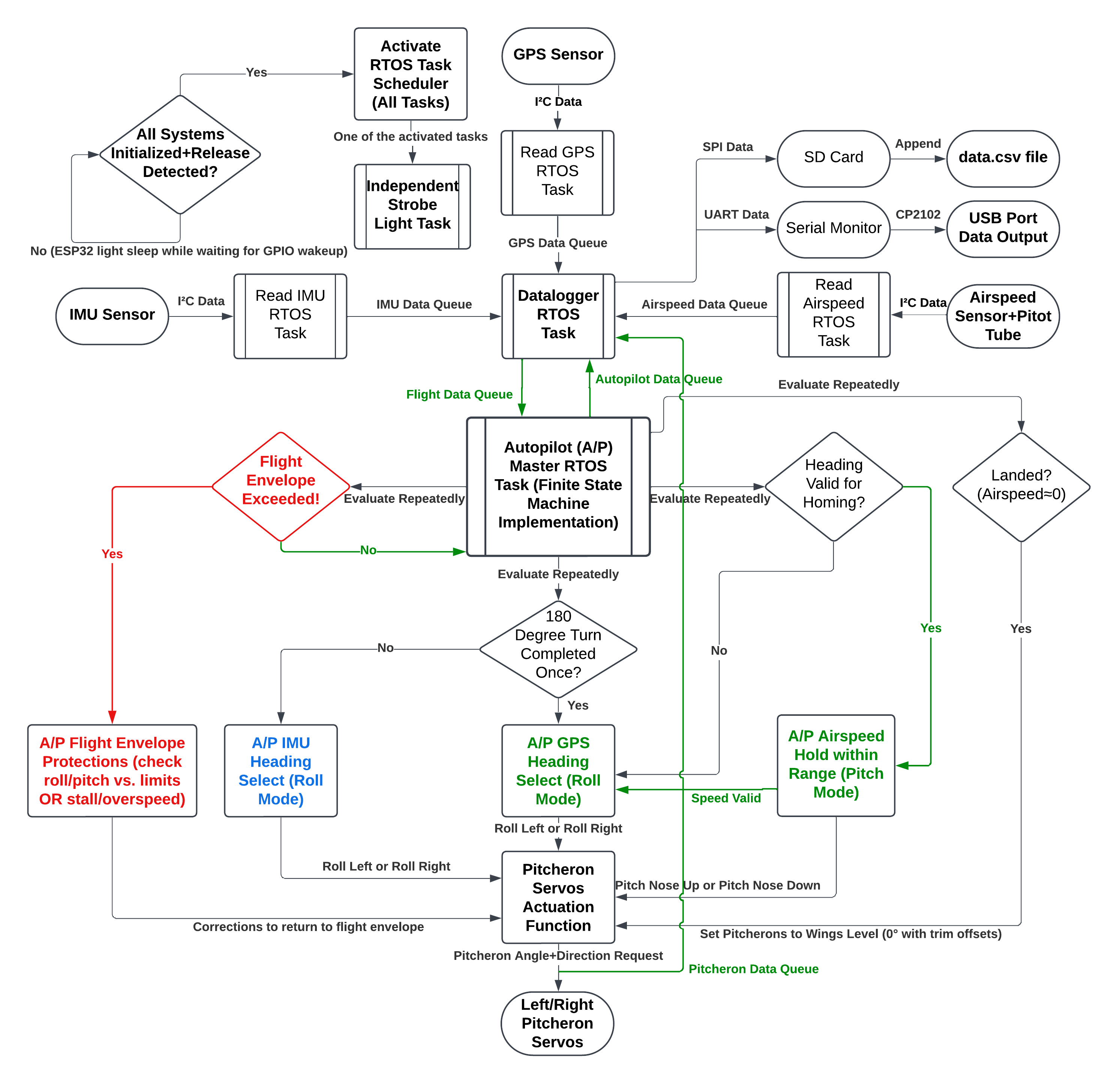
The ESP32's control software uses FreeRTOS to manage real-time tasks in parallel on its dual-core processor. The flow chart shows the system behavior after release detection, including concurrent tasks for sensor updates, servo actuation, strobe control, and SD card logging. The structure supports state transitions (such as the 180° turn to GPS homing), and enables safety features like flight envelope protection to prevent an aerodynamic stall.
Final Glider Assembly
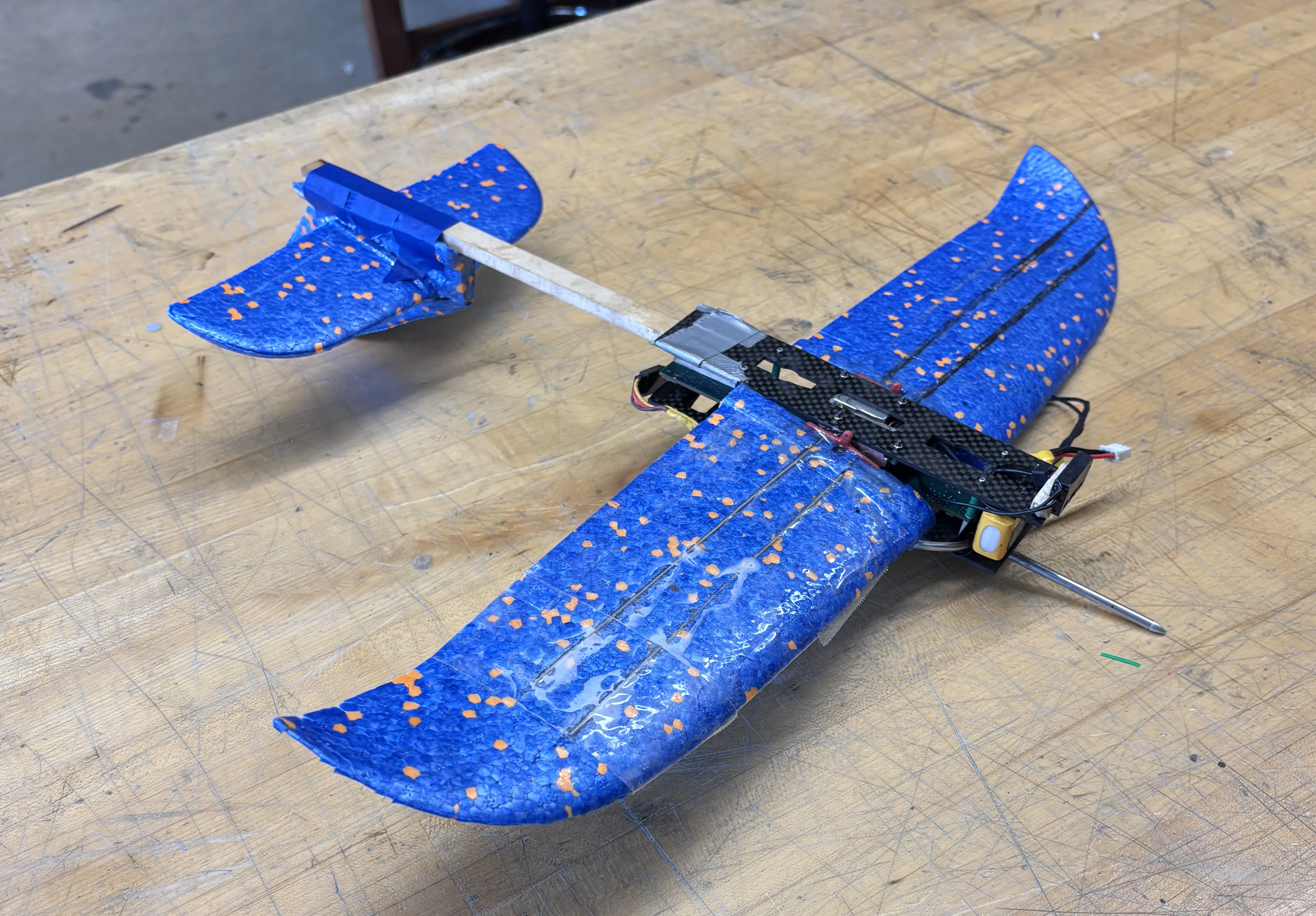
Here is an image of the final glider assembly.
Sources:
[1] 2024-25 Design, Build, Fly Rules Summary, www.aiaa.org/docs/default-source/uploadedfiles/ aiaadbf/resources/dbf-rules-2025.pdf?sfvrsn=7e2ef7d8_6. Accessed 17 Dec. 2024.