Subsystems

Like a System, but smaller. Here we outline the three major subsystems.

Ranging

The ranging subsystem uses RF transmission flight times between two DWM1000 chips to calculate the distance between them. The board configured as the Initiator cycles between up to four different Responders, each with a unique address, to get the distance between itself and the four other boards. The code used to calculate the distances is provided by Decawave, and is available for download from the Decawave Software Page . The DWM1000 is integrated with our PIC32 through an SPI interface.
I2C Communication Protocol

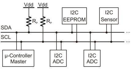
The RFC wanted us to use I2C protocol to communicate between our system and their QB. I2C needs at a minimum three connections between a slave and a master to communicate properly: an SDA line, SCL line, and GND. The SDA line transmits data, the SCL is a common clock, and GND is ground. Each SDA and SCL line must be pulled up to 3.3V through 2.4k resistors. Our molex connector uses a fourth pin from our board to the QB to pull these up on a VCC pin. The advantage of using I2C protocol over SPI or some other type of communication, is that multiple slave devices can be linked to one master over these three common lines. In other protocols, each slave device needs their own lines to communicate with the master, making wiring messy and cluttered very quickly.

Trilateration and Positioning

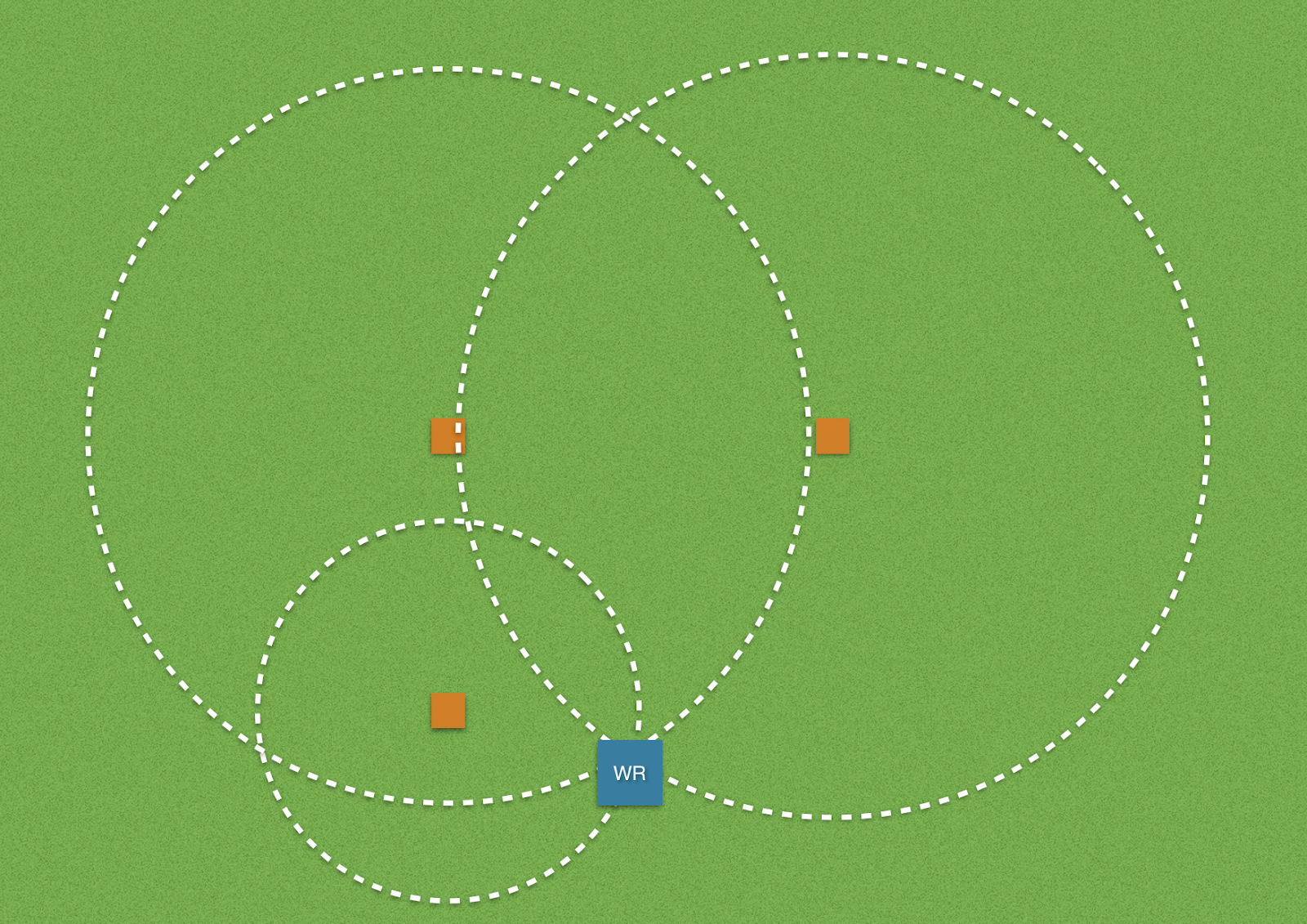
Trilateration is done by first sending a signal from one pylon to determine how far the distance is from the wide receiver to the pylon. This distance is referred to as the radius of the circle made by the pylons signal, but the receiver could be anywhere on the circle. Once this distance is determined, the next pylon sends a signal and the radius of that circle is the distance from said pylon to the receiver. Now both circles intersect at two different locations, meaning the receiver could be at either position. To determine which of the two the receiver is at, the third pylon repeats this process and the radius of that circle is the distance from the receiver to said pylon. This determines which of the two former intersections the receiver is located at, thus returning an x and y coordinate of the receiver with respect to the pylons. These calculations are done in C, with code that will be injected into the initiator code on the PIC32.