Hardware Design
PCB, sensors, motors, and power.
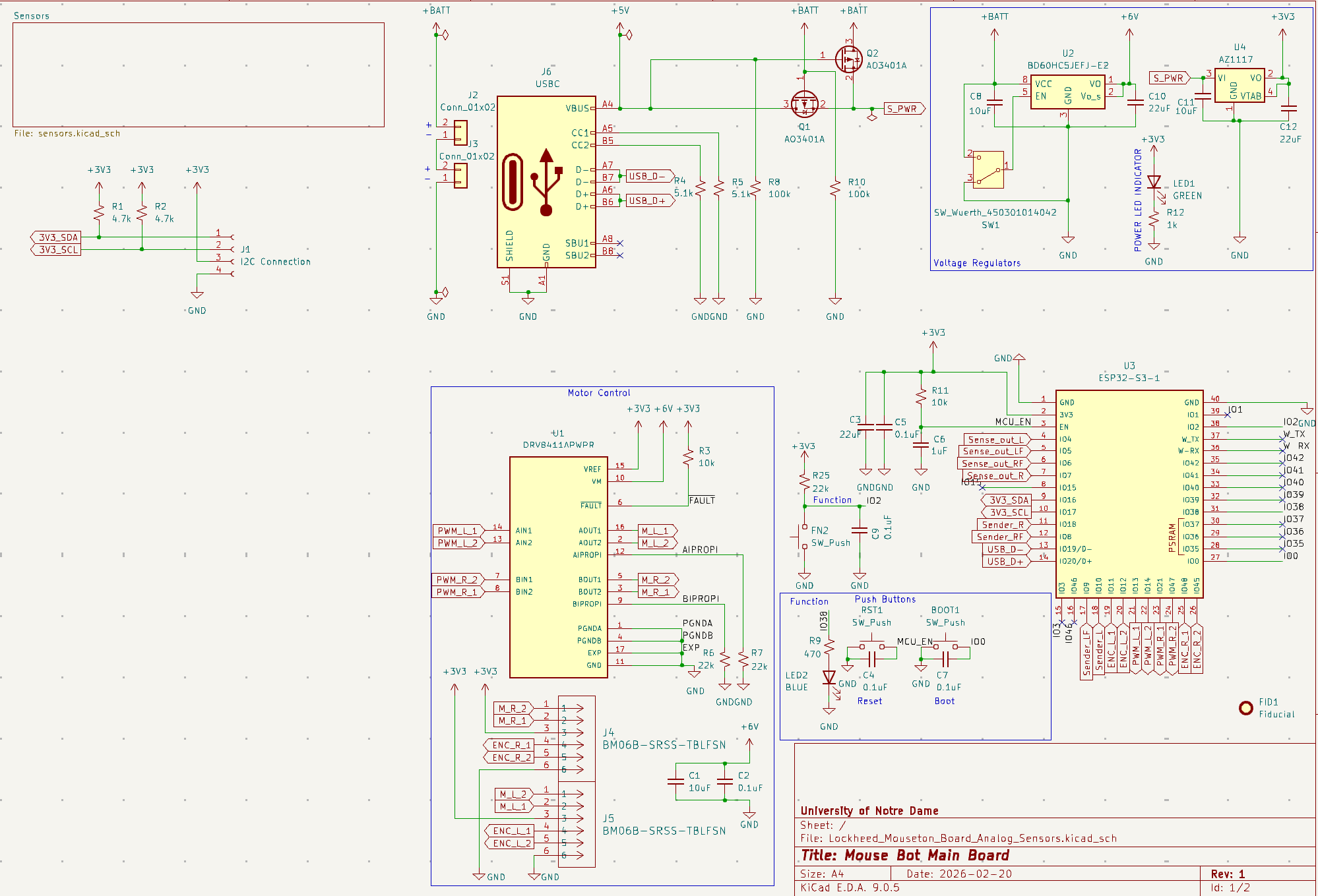
The mouse is built around a custom PCB carrying an ESP32-S3 microcontroller, IR distance sensors for wall detection, encoder-equipped DC gearmotors, an H-bridge for motor drive, and the power regulation needed to run all of the above from a single battery pack.
System Block Diagram

Microcontroller
An ESP32-S3 serves as the main processor. It handles ADC reads from the IR sensors, generates the PWM signals for the motor driver, reads the wheel encoders, and runs the maze-solving algorithm. The S3 was chosen for its ample peripheral count, dual-core architecture, and easy programming environment.

IR Distance Sensors
Three IR emitter/phototransistor pairs are positioned to read the front, left, and right walls of the current maze cell. Each sensor is read through an ADC channel on the ESP32-S3 and converted to a distance using the calibration curve described on the Software page.

Motor Drive
Two DC gearmotors with integrated quadrature encoders provide the drivetrain.
An H-bridge driven by PWM from the ESP32-S3 controls speed and direction for
each wheel independently, and the encoder counts feed back into the closed-loop
straight-drive and turn routines in motion.cpp.

Power
The mouse runs from a battery pack feeding two regulated rails: a higher voltage rail for the motors and a 3.3 V rail for the microcontroller and sensors. The block diagram below shows how power is distributed across the board.

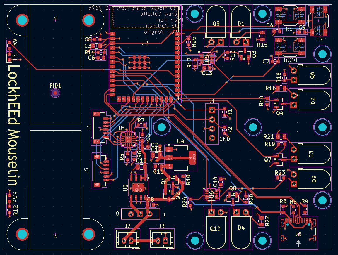
PCB
All of the above is integrated onto a single custom PCB sized to fit the chassis. The board hosts the MCU, sensor analog front end, motor driver, power regulation, and connectors for the motors, encoders, and battery.