Hardware Design
The Microcontroller
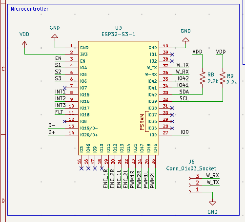
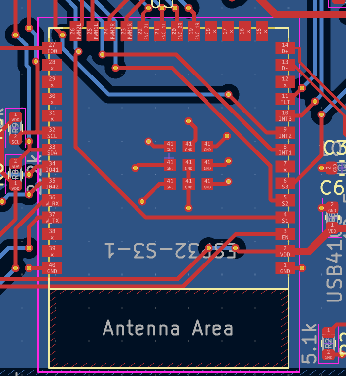
To act as the brains of our mouse, we chose the ESP32-S3-WROOM Microcontroller with 4MB of Flash and no PSRAM (N4). We chose this microcontroller because it falls in the same family as the one on the practice mouse (ESP32-S3-WROOM, N16R8), and we had no issues or desires beyond what that microcontroller could do.
Batteries and Voltage Regulators
Power Source: Our team chose to use two 3.7V LiPo Batteries as the wireless power source for our design, supplying a total of 7.4V to the entire board. To regulate this, we chose two separate voltage regulators to supply their respective peripherals with the appropriate amount of power. The LD1117 regulated the motors' power supply from the input value of 7.4V to a usable 5V, and the AZ1117 regulated the input power to a value of 3.3V for the remaining peripherals (OLED, microcontroller, ToF sensors, DRV8411 motor driver).

USB-C Connection: We used an EIH-stocked USB-C connection to power our board via our computers to run simple debugging tests and upload code to the microcontroller.
Motor Control
Motors: We selected the Adafruit N20 DC Motor with a 50:1 gear ratio because it had the appropriate torque and speed necessary for our requirements. This motor also includes an encoder, making tracking encoder counts much easier. Prior to the 50:1 gear ratio, we tested 298:1 motors from the same family, but they were much too slow.

Motor Driver: We selected the DRV8411A motor driver to independently drive both motors simultaneously, supporting forward, reverse, and braking. It provides more than enough current and voltage from the motor voltage regulator to the motors themselves.


Sensors
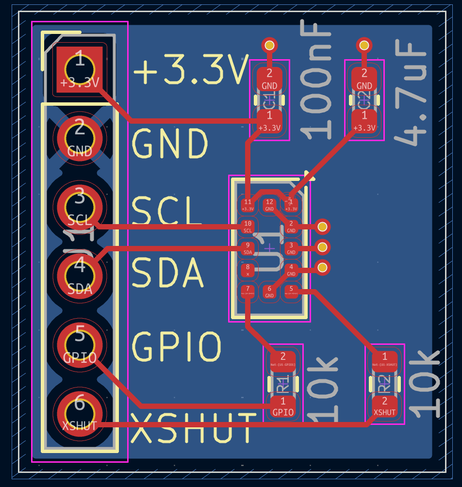
Time of Flight (TOF) System: We selected the VL53L0X Time of Flight sensor for distance tracking. We used three in total: one on each side and one in the front. Though the refresh rate of ToF sensors is significantly slower than some analog sensors, they pair well with our slower motors and are easier to program and more resistant to ambient changes in lighting. We designed a breakout board for the sensors because of their need to be perpendicular to the main PCB.

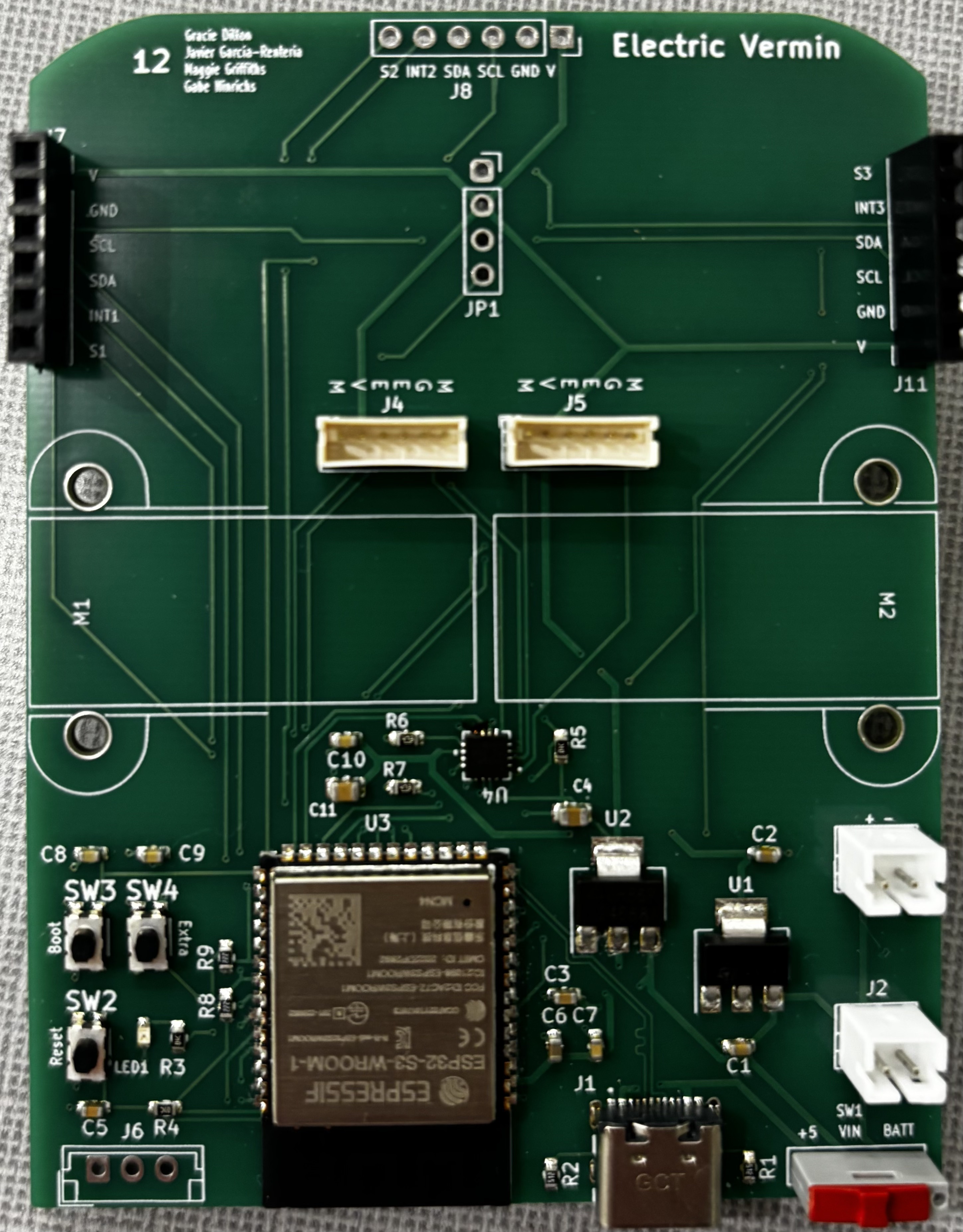
Final PCB Design